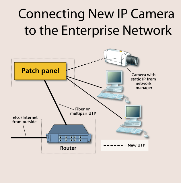
Although this example uses a network camera, the same principles apply to any type of IP-addressed electronic security device, such as video servers, access control interfaces, or alarm transmitters. Although there may be unused RJ-45 sockets available in the work area, and the temptation great to connect the camera to them, this should be avoided. It is too easy for a person to unplug the camera’s network connection from the wall, and it’s also probable that at some point the client will need that particular network socket for the enterprise network or a telephone connection. The security contractor should install new UTP cable from the camera location to the horizontal cross-connection room, placing male RJ-45 connectors on each end to plug into the camera and the patch panel within the horizontal cross-connect.
Many of today’s network cameras are powered by low-voltage AC, supplied by a plug-in transformer. Security installation technicians need to make sure that the AC outlet selected is not on a switched circuit, which can kill power to the camera. They also should ensure that the location for the plug-in transformer is not easily accessible, which would allow someone to inadvertently or deliberately unplug the transformer.
Some cameras can be powered with low-voltage DC current, which in some cases can be transported on the unused pairs of the UTP cable connecting the camera to the cross-connection location.
If given the OK by the client’s network administrator, the network video camera can be connected to an unused patch panel port in the horizontal cross-connection room. Assuming the selected patch panel port is properly terminated, the network camera is now functional on the network, provided it has been programmed with a network-compatible IP address. In the case where the camera is being connected to the network along with other enterprise computers, the system administrator will provide a correct IP address for the security dealer to program into the camera.
Network administrators may be unwilling to allow the connection of “foreign†devices on their network due to security and bandwidth considerations. If the electronic security company is denied access to the common enterprise network for its devices, the use of “parallel†network cabling can provide the benefits of using some of the existing cabling in the client’s location, while increasing the security of the alarm/surveillance/access control systems’ communications.
Parallel Networking
To conceptualize parallel networking, consider an interstate highway connecting two interchanges. While there is the main highway, perhaps three lanes in each direction, there is also the lesser-used two-lane access road running along both sides of the highway.The same concept is available in structured cabling systems that were installed with currently unused conductors, either fiber or copper, between the horizontal cross-connection points and the main. The “access road†between the connection points may well be unused, readily available, and perfect for security system network connection. And contrary to the highway example above, the unused conductors between connection points will likely be of equal potential bandwidth to the main network.
Isolation of the electronic security network devices from the client’s enterprise network provides many benefits. As the signals are isolated, there is no impact on the enterprise’s bandwidth usage; the security system can’t be blamed for network slowdowns. An isolated security network is harder for insiders to hack, as their computers are not electrically connected to it, so inside personnel cannot easily dial up a security device to see how it works. Politically, an isolated security network can produce better relations with the client’s IT manager. The network manager provides the use of otherwise unused conductors between connection points, and the security installation company takes responsibility for all addressing, networking issues, etc., for the security devices. In many ways parallel networking of security devices is preferable to sharing bandwidth with the enterprise.
Parallel Network Testing
The first step is to find out if unused backbone conductivity is available, and to obtain the approval of the client’s network manager for its use. The next step is to test the quality of the proposed conductors, whether copper or fiber. In the case of UTP, proper terminations and bandwidth capability can be verified with a fairly inexpensive tester ($125 or so), that will confirm that the jack sockets at each end have been properly connected, and that the cable can pass 10/100 Mbps Ethernet. This assumes that the spare conductors have been previously terminated onto RJ-45 jacks at both ends; if not, female jack sockets will need to be installed.
If the conductors are fiber, shining a standard flashlight into one end of the fiber can confirm that the fiber isn’t internally broken, provided that the light comes out of the other end of the fiber being tested. If the light doesn’t pass through, it is likely that one or both of the fiber connectors were poorly installed and/or defective, and needs replacement.
Warning: It is common for currently unused fiber strands to be either un-terminated, or to have poor quality connectors installed by the original contractor. Remember that these fiber strands were planned to be spares, so they likely have never been connected to the network, so their potential defects have never been exposed.


