MORE POWER


When devices malfunction, a lack of adequate power is to blame. This lack of power may be attributed to insufficient power supplied by the system, or failure of the supplied power to reach the applicable device.
Understanding the flow of electrons through components and wiring will help you design, apply, install, service and troubleshoot alarm systems.
In the most basic sense, electricity is comprised of three required components: voltage, current and resistance.
Electric current is charge in motion. It can be any charge, such as electrons, protons or ions. The unit for current is the ampere (amp), which is named in honor of French physicist Andre Marie Ampere (1775-1836).
In electrical formulas, the symbol for current is I, which stands for the intensity at which current flows. Current is a measurement of the amount and rate of free electrons flowing in a circuit. One ampere is equal to one coulomb flowing past a given point in one second.
If a conductor is placed between two unequally charged bodies, electrons will move from the more negatively charged body to the more positively charged one. Current will travel from the negative side of a power source through the wire and any devices and back to the positive side of the power source.
Voltage is the electrical pressure, or force, that causes that charge to move. You might say that the voltage pushes the current through the circuit.
The resistance of a circuit is the measure of how easily electrons flow through it. Resistance is opposition to current and is caused by a lack of available charge carriers or difficulty in moving charge carriers through a material.
The unit of resistance is the Ohm, which is named in honor of Geog Simon Ohm (1787-1854), a Bavarian born German physicist. The Greek capital letter omega (w) is used as the abbreviation for the word ohm, such as writing that a wire has 1000 w or 1000 Ohms of resistance. R is the symbol for resistance in mathematical formulas such as Ohm’s law.
The resistance of a wire decreases as it becomes thicker and increases with its length. In alarm circuits, a break in the wiring provides no path for current to flow and creates infinite resistance.
A small wire provides a high resistance or small path for current to flow. A large wire provides a lower resistance or bigger path.
Increasing the pressure or voltage to a circuit will cause more current to flow past a resistance. Removing voltage will result in less current flowing past that same resistance. Resistance is any load that opposes current flow. A load is anything that takes or draws current.
Components, wire and connections create resistance. Note that excessive resistance can mean trouble! All alarm devices such as motion detectors, audio processors, even simple switches, have some resistance. The resistance may or may not be enough to be significant.
In modern alarm systems, there is often a need to limit current in an electronic circuit. The need can be met with a resistor. A resistor is a device that is made to offer a specific and desired amount of resistance to the flow of electric current. One such example is the end-of-line (EOL) resistor included in today’s alarm detection circuits.
By installing the EOL resistor properly at the end of a line, the system circuitry has the ability to determine the correct amount of current flow in the applicable circuit. Due to that predefined determination, the circuitry has the ability to interpret that an increase in current flow possibly means a short circuit. It may be caused by an errant staple, or someone attempting to circumvent the detection device.
Conversely, a decrease in current flow is interpreted as a break in the detection circuit and the result of an intrusion device activating. An enhanced explanation of these principles is covered later in this article.
Understanding the relationship between voltage, current and resistance aids the technician by explaining what certain readings on their multimeter are showing them.
Ohm’s Law is a formula to show the relationships between volts (E), ohms (R) and amps (I).
Ohm’s Law can be used to compute the value of any variable within the formula if the other two are known.
Some simple examples of the relationships between these three items are reflected in these several examples:
- If I = 6 amps and R = 2 ohms, then E = 12 volts
- If E = 8 volts and R = 4 ohms, then I = 2 amps
- If E = 9 volts and I = 3 amps, then R = 3 ohms
- If I = 3 amps and R = 2 ohms, then E = 6 volts
- If E = 8 volts and R = 8 ohms, then I = 1 amp
Typical Alarm Circuits
There are two basic circuits used in today’s alarm systems, and which type is being used will determine how those circuits impact the relations between voltage, current and resistance.The two basic circuit types are referred to as series circuits and parallel circuits. In a series electrical circuit, all electrons leave the power source at the same point and travel the same path back to the power source.
In a parallel electrical circuit, all current leaves the power source from the same point, but a portion of the current takes one path while another portion of the current take a different path. All paths return to the source.
Wiring determines the nature of the circuit: one path = series circuit, multiple paths = parallel circuit.
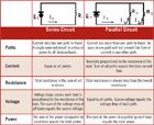
Series Circuit Profile:
- Resistance will be additive — RT
= R1 + R2 + R3
The total resistance can be found by adding the resistances of all the devices in the series circuits together. - Current flow will remain the same — IT=
I1= I2 = I3
Current flow stays the same at all points in the series circuit. - Source voltage will be equal to the sum of all the voltage drops — ET = E1 + E2 + E3
- The source or total voltage can be found by adding together all of the voltage dropped or used by each device in the series circuit.
- If you raise E, I will increase.
- If you raise R, I will decrease.
- If you lower E, I will decrease.
- If you lower R, I will increase.
Parallel Circuit Profile:
- In a parallel circuit, IT divides (branches) with parts of IT flowing through the parallel loads. — IT = I1 + I2 + ... + In
- In a parallel circuit, all the voltage drops are equal to each other and are the same as ET. — ET = E1 = E2 = ... = En
- In a basic parallel circuit, the RT will be less then the smallest individual resistor value in the circuit.
RT = R1 x R2 / R1 + R2
If the parallel circuit includes three or more resistors in parallel, the formula is:
RT = 1 /
1/R1 + 1/R2 + 1/R3 + … + 1/Rn
This formula will compute RT for any number of loads. Rn is the last resistor in the string. The n can be any number from one on.
Types of Series Circuits
Open Circuit — If there is a break anywhere in the circuit, no current will flow. The break is called an open circuit. Open circuits are caused by breaks in the wire or by burned out components.Short Circuit — A short circuit is any path that diverts the flow of current from one or more of the circuit loads. This wire provides a current path that bypasses resistor R2. A short circuit usually increases the flow of IT (total current).
Types of Parallel Circuits
Open Circuit — If there is an open circuit in one branch of a parallel circuit, no current will flow along the open path. In the illustration, the break (open circuit) is in the R2 branch; the current I2 will stop flowing while the current I1 will continue to flow through R1.Short Circuit — A short circuit across any leg of a parallel circuit will cause the entire source current (IT) to flow through the short. For example, if ET = 12V. And the wire causing the short = .001 ohms. The total current would be: IT= ET/short. 12V/.001 ohms = 12,000 amps. 12,000 amps is an enormous amount of current. This amount of current would melt the short or damage the power source.
Open Circuit Causes
Opens on this type of circuit account for the largest percentage of faults. What conditions may cause an “open” in the circuit? The major causes of open circuits are:- Wire breaks (ripped or cut).
- Bad splices.
- Cold solder joints.
- Loose connections.
- Wire fatigue due to overflexing.
- Defective wire.
Short Circuit Causes
Shorts on a closed loop circuit will bypass devices connected to the wiring. Any event occurring past the short will not be seen by the system. Some of the most common causes of shorts are:- Staple cuts.
- Sharp edge cuts.
- Improper splices.
- Moisture.
- Cold flow of wiring.
Where Is the Power?
You may see how all this applies to detection circuits and determining how (or why) a particular device may or may not activate the alarm system, or cause an alarm to activate, but how does all this affect the system power?To oversimplify it, the power wiring to all of your security detection devices (such as PIRs, glass break detectors, etc.) are in essence one huge parallel circuit. As such, two principles of a typical parallel circuit can affect the proper operation of your detection devices.
1.Too Many Devices — Too Little Current Available
Consider that in a parallel circuit (all with equal path/device resistance) the current available is divided equally among all these available paths. This potentially results in an inadequate amount of current available when the device needs to activate. Some examples of this occurring are as follows:
a. Upon alarm activation — other detection devices also begin to signal activation (even though they are in different areas or zones). This occurs when the activation of one device results (increased current requirement) in other devices falling below their minimum necessary current required to operate. Subsequently, they begin to fault due to a lack of sufficient current. This situation also can be aggravated by the increased current draw of the system sounding devices.
b.Intermittent loss of picture from outside video cameras, at night, during the winter months. During the winter months, closed circuit television (CCTV) cameras installed inside housings with heaters sharing the provided power can experience difficulties if the heater current draw was not added to the necessary current needed to operate the camera simultaneously.
2. Adequate Power Just Too Far Away
When designing a security system, the distance from the power source and the powered device needs to be an integral part of the design consideration. Far too often, a decision to centralize all of the power for convenience results in issues with devices located at remote locations of the system.
Specifically, the resistance of the wiring needs to be calculated as the distance from the power becomes greater and greater. In extreme cases, half the available current can be lost (dropped) across the resulting wire resistance.
This wire resistance ultimately results in the amount of resistance for that particular circuit increasing to levels that may affect the remote device or all the devices if the levels are severe enough.
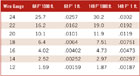
The chart below shows the resulting wire resistance for the various gauge wires at different distances and temperatures.
Wire sizes are standardized throughout the United States and numbered in American wire gauge (AWG) units. The gauge of the wire is inversely proportional to the size of the wire.
A 4-gauge wire is larger in diameter than 26-gauge wire. For every drop of three gauge numbers, the area of the wire doubles. Because electrical conductivity is directly proportional to the conductor’s area, decreasing the gauge of the wire by three also cuts the resistance in half, assuming the length of the wire is unchanged.
As we have already discussed, devices may be adversely affected by undersized wiring resulting in:
- Reduced voltage available to power supplies.
- Reduced charging circuit output; therefore reduced battery charge.
- Reduced circuit (loop) voltages and currents, causing improper operation.
- Reduced auxiliary output power, thereby causing erratic operation.
- Increased heat build-up on input wiring.
About this Article:
This article was contributed by the National Training School (NTS) of the National Burglar & Fire Alarm Association (NBFAA), Irving, Texas. The NBFAA is the largest trade association in the United States with the primary purpose of representing, promoting and enhancing the growth and professional development of the electronic life safety, security and systems industry. Member companies specialize in a wide spectrum of services to commercial and residential consumers, including security and fire alarms, video surveillance, access control and monitoring.Significant portions of this article were excerpted from the NBFAA National Training School’s Level One Certified Alarm Technician course. Founded by the NBFAA 22 years ago, the National Training School (NTS) is the definitive source for professional development and training for the industry and delivers curriculum most recognized to meet state licensing requirements. Taught by top industry professionals, nearly 30,000 students have completed NTS courses and thousands have been certified. For more information, visit the ‘Professional Development’ section of www.alarm.org or call (866) 636-1NTS or (866) 636-1687.
Looking for a reprint of this article?
From high-res PDFs to custom plaques, order your copy today!


