SDMmag logo
search
Go to Ask SDM AI
cart
facebook twitter linkedin youtube
  • Sign In
  • Create Account
  • Sign Out
  • My Account
SDMmag logo
  • NEWS
  • PRODUCTS
  • TOPICS
    • Access Control & Identification
    • Integration & Network Solutions
    • Life Safety & Fire Alarm
    • Monitoring
    • Smart Home
    • Trends & Industry Issues
    • Video Solutions
  • COLUMNS
    • Digital Shuffle
    • Editor's Angle
    • Insider News & Business
    • Integration Spotlight
    • Marketing Madmen
    • Security & the Law
    • Security Comings & Goings
    • Security Networkings
    • Technology @ Work
    • Technology Solutions & Skills
    • SIA Waypoints
    • Cybersecurity Chronicle
  • EXCLUSIVES
    • Annual Industry Forecast
    • Dealer of the Year
    • Project of the Year
    • SDM 100
    • State of the Market Series
    • Systems Integrator of the Year
    • Top Systems Integrator Report
    • TMA Excellence Awards
  • BLOG
  • MEDIA
    • Videos
    • Podcasts
    • Polls
    • White Papers
  • EVENTS
    • Industry Calendar
    • Webinars
  • MORE
    • Classified Ads
    • Newsletters
    • SDM Store
    • State of Security eBook
    • Sponsored Insights
  • BUYERS GUIDE
    • Buyers Guide
    • Take a Tour
  • EMAG
    • eMagazine
    • Archive Issues
    • Monitoring Today
    • Advertise
  • SIGN UP!

Testers and Their Uses

By David Engebretson
December 11, 2003
Fiber optic technology offers a lot of flexibility for transmitting video surveillance and access control information. Fiber cables are abundantly installed in corporate and commercial facilities throughout the world, making it a favorable choice for signal transmission for security systems.

A fiber optic link provides a path for light signals to travel between a transmitter and a receiver. For proper performance, this path must be free of defects and installation errors; otherwise, these may interfere with the light pulses as they pass through the cable.

There are many different devices and methods used to assure the quality of a fiber optic link. Just as automobiles have gauges and warning lights to indicate different engine conditions and mechanical problems, the testers used by a fiber optic technician provide different measurements and indicators of the usability of the fiber link being tested.

VISUAL TESTERS

To function properly, a fiber link must be “continuous,” meaning that it is not broken internally, either in the connector ends or within the fiber cable itself. Flashlights and visible lasers are used to perform this test. Visual testing yields a simple “no go” test. If the light or laser isn’t visible at the other end of the fiber link, then the fiber is unusable in its present state and requires further testing and repair.

A flashlight is the simplest and most inexpensive means to test the continuity of a fiber optic cable. A red lens in a standard flashlight provides easy viewing.
Flashlights: The least expensive and simplest fiber continuity tester is the common flashlight. By shining the flashlight into one end of a fiber link, visible light will be injected into the fiber. If the light is visible at the opposite end, then you will know that the fiber link is continuous.

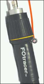
Flashlights can be used to test multimode fiber links as long as three miles. This distance depends on the light power of the flashlight being used.

Fiber optic manufacturers supply flashlights with special adapters which allow direct connection of typical connector types, such as ST and SC, to the flashlight’s lens. The insertion of a colored film, such as red or green, makes the light more visible at the other end of the fiber link.

Manufacturers of fiber optic transmission equipment for the electronic security industry build their products to perform with a large percentage of potential signal loss between the transmitter and the receiver. Typically, a standard set of such transmission devices, also called “optoelectronics,” can function with as much as a 95 percent signal loss. Because of this wide performance margin, a fiber link that has been tested with a flashlight and seen to be continuous most likely will work fine for its intended use. In many cases, the flashlight is the only tester that a fiber optic technician may need. If the flashlight does not shine through the fiber link, a more sophisticated tester will be needed to find the location of the break.

Visible Laser Testers: Visible lasers produce a more powerful light and can provide more information to the technician than a flashlight. By coupling the fiber link to a visible laser, problems with connectors, breaks in the fiber near connectors or splices, and some bend radius violations can be located.

A visible laser tester (red laser light) indicates the location of a break under the fiber jacket.
Most visible lasers provided by fiber tester manufacturers operate at 660 nanometers (nm), which is within the range of human vision. Fiber optic transmitters use LEDs or lasers at standard frequencies of 850, 1300, 1310, or 1550nm, which are beyond our eye’s ability to see. Most visible lasers can travel 600 to 800 ft. in a fiber link.

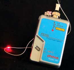
Testing with a visible laser will show the location of breaks within a fiber strand, provided that the outside jacket has been removed. A problem connector may be detected with the visible laser, provided that the connector has a plastic ferrule tip.

Looking for quick answers on security topics? Try Ask SDM, our new smart AI search tool. Ask SDM →

Manufacturers produce visible laser testers with various power levels and price points. A generic laser pointer, such as used in making presentations, can substitute for a much more costly fiber-specific testing device.

Both the visible laser testers and the invisible laser light sources used in some fiber transmitters can cause eye damage if repeatedly viewed. A technician always should view the reflected light from the laser, as opposed to viewing the light directly.

QUALITY TESTING OF FIBER LINKS

Although they can provide an indication of the usability of a fiber link, visible testers give a technician a limited amount of information. For a fiber link to be used over long distances or with maximum signal throughput, testers that produce a quantitative measurement of the fiber link’s quality are needed.

In this Optical Loss Test Set, the light source (left) and power meter (right) are connected with test jumpers to a fiber link.
Optical Loss Test Set: An Optical Loss Test Set, which is comprised of a light source and a power meter, is used to perform a complete, end-to-end quality test of a fiber optic link. The light source has an LED (multimode) or laser (singlemode) invisible light output, and transmits a continuous light wave at one of the standard fiber optic frequencies. This light energy is coupled into one end of the fiber link being tested. At the other end, the power meter measures the amount of light power it detects coming from the light source, and displays its measurement in decibels (dBs).

Two technicians must set up and connect the light source and power meter at opposite ends of the link, and use consistent procedures in order for test results to be accurate. Specifying bodies such as the EIA/TIA (Electronics Industry Association/ Telecommunications Industry Association) detail the exact procedures to be used when setting up and executing optical loss tests. The most commonly accepted testing methods are included in the EIA/TIA 568 standards for communication wiring.

Power meters can be very simple, with the dB light power value appearing on the meter’s display. More sophisticated testers can electronically record test values, download them to a computer, and provide other features. All optical loss testing results should be documented and saved.

Because of small differences in tolerances, a fiber link may have lower optical loss when measured from one end or the other. As many fiber links are installed but not immediately connected to transmission equipment, the standards require that fiber links be optical-loss tested in both directions that signal transmissions may travel.

An important usage of the power meter is for testing the output of a fiber optic transmitter. By connecting the power meter directly to the transmitter, it can be quickly determined whether the transmitter has the proper amount of light output.

The Optical Loss Test set is the generally accepted final test for a finished fiber optic link.

The OTDR trace provides information about a fiber link’s distance and the location and severity of loss events.
Optical Time Domain Reflectometers: Neither the visual nor the optical loss testers can inform the technician of the location of a break or excessive bend in a fiber link. This information is available only by using an Optical Time Domain Reflectometer (OTDR).

This device injects a pulsed laser light into one end of a fiber link, and displays the light energy reflected back to the tester from connector sets, splices, excessive bends, and the end of the fiber link itself. These testers operate at the standard wavelengths used in fiber optic transmissions.

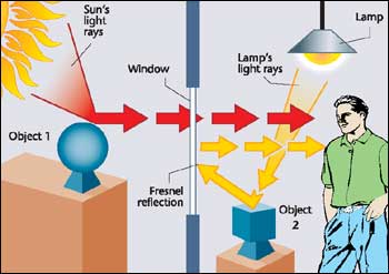
Connector sets and mechanical splices reflect light energy back to the OTDR because of Fresnel reflection. When a light wave passes from one medium to another, approximately 4 percent of the light energy is reflected back. This effect can be easily seen by looking out a window. You can see the outside, as well as reflections from within the room.

The lengths of fiber between connector sets will also reflect light back to the OTDR due to the effects of Rayleigh (ray-lay) scattering. Light energy traveling through the fiber core collides with water molecules, scattering some of the light energy back towards the OTDR.

Light reflects as it passes from one medium to another, allowing the viewer to see reflections from the room as well as the object outside the glass.
The combination of Fresnel reflections and Rayleigh scattering provides the information needed for the OTDR to plot a trace, or picture of the fiber being tested. The OTDR plots the information along two axes, with the vertical indicating dB of light power, and the horizontal indicating distance to a point in feet or meters.

OTDR traces require interpretation by a technician, as there can be circumstances that may hide or mask a potential fiber problem. For example, OTDRs generally cannot distinguish between two connector sets or splices that are within 50 ft. or less of each other.

The OTDR is a powerful testing tool. One of its advantages is the ability to ensure the quality of the entire fiber link without testing from both ends – a big plus when testing a fiber that is many miles long.

The OFL provides a read-out of distance to a loss event. Some end users will require OTDR traces of completed fiber links as part of their contracted testing procedures. Whether required or not, OTDR traces should be stored for later comparison in the event of a fiber break or problem.

The OFL provides a read-out of distance to a loss event.
Optical Fault Locator: A lower cost version of an OTDR is called an Optical Fault Locator (OFL). This tester is the same as an OTDR, but has a read-out of event locations instead of the plotted trace.

OFLs are less expensive and easier to use than OTDRs. However, OFLs do not provide the detail available with the OTDR’s trace.

Not all of these testing devices will be needed for every installation. A simple flashlight can be used to test the fiber link for continuity, and there is no reason not to simply connect the transmitter and receiver to the tested fiber link and complete the installation. With the addition of an Optical Loss Test Set, a technician can test fiber links for loss values, and transmitters for functionality.

Share This Story

Looking for a reprint of this article?
From high-res PDFs to custom plaques, order your copy today!

Dave Engebretson is the president of Slayton Solutions Ltd., which provides fiber optic, IP networking, and cable termination and testing training for our industry. Catch his speeches at the ADI Expo in your area and win a prize if you can identify the 1970s era rock song that is his ringtone. See his work at slaytonsolutionsltd.com.

Recommended Content

JOIN TODAY
to unlock your recommendations.

Already have an account? Sign In

  • SDM 100

    SDM 100: Top 100 Security Dealers of 2026

    The top 100 security dealers navigated a complex...
    SDM 100 Report
    By: Karyn Hodgson
  • Security camera

    State of the Market: Video Surveillance

    As video surveillance shifts from siloed systems to...
    Exclusives
    By: Brianna Wilson
  • 2026 Industry Forecast

    SDM 2026 INDUSTRY FORECAST

    Rapid technology advances meet shifting economic...
    Exclusives
    By: Karyn Hodgson
Manage My Account
  • SDM Newsletters
  • Online Registration
  • eMagazine Subscriptions
  • Subscription Customer Service
  • Manage My Preferences

More Videos

Sponsored Content

Sponsored Content is a special paid section where industry companies provide high quality, objective, non-commercial content around topics of interest to the SDM audience. All Sponsored Content is supplied by the advertising company and any opinions expressed in this article are those of the author and not necessarily reflect the views of SDM or its parent company, BNP Media. Interested in participating in our Sponsored Content section? Contact your local rep!

close
  • Doctor examining child patient with mother present in medical clinic
    Sponsored byHID

    The Human Side of Hospital Security: How Modern Visitor Management Protects People First

Popular Stories

Video surveillance camera

Why Video Health Monitoring Is a ‘No Brainer’

ESA Board of Directors Q2 26 Elections

Electronic Security Association Announces 2026 Board of Directors Election Results

TMA & SDM Logos

Becklar, Elite & Puget Win 2026 TMA/SDM Monitoring Center Excellence Awards

SDM Dealer of the Year 2026 Promotion

Poll

What’s the most promising trend in the industry?

What’s the most promising trend in the industry?
View Results Poll Archive

Products

Physical Security Assessment Handbook An Insider’s Guide to Securing a Business

Physical Security Assessment Handbook An Insider’s Guide to Securing a Business

See More Products
SDM 100 2026 Rankings

Related Articles

  • VIDEO ANALYTICS: WORKING SMART FOR YOUR CLIENT

    See More
  • SDMs Field Guide to IP Alarm Transmitters

    See More
  • Conducting Business

    See More
×

Be in the forefront of security intelligence when you receive SDM.

Join over 10,000+ professionals when you subscribe today.

SIGN UP TODAY!
  • RESOURCES
    • Advertise
    • Contact Us
    • Directories
    • Store
    • Want More
  • SIGN UP TODAY
    • Create Account
    • eMagazine
    • Newsletter
    • Customer Service
    • Manage Preferences
  • SERVICES
    • Marketing Services
    • Reprints
    • Market Research
    • List Rental
    • Survey/Respondent Access
  • STAY CONNECTED
    • LinkedIn
    • Facebook
    • YouTube
    • X (Twitter)
  • PRIVACY
    • PRIVACY POLICY
    • TERMS & CONDITIONS
    • DO NOT SELL MY PERSONAL INFORMATION
    • PRIVACY REQUEST
    • ACCESSIBILITY

Copyright ©2026. All Rights Reserved BNP Media, Inc. and BNP Media II, LLC.

Design, CMS, Hosting & Web Development :: ePublishing