Success Stories in Digital Video Conversion
Children’s Health Care of Atlanta
When Children’s Health Care of Atlanta, Ga., made the decision to employ Tech Systems to upgrade its extensive video surveillance system to a networked DVR-based system, a key goal was to streamline and enhance the task of retrieving image archives.“The amount of time to find an incident went down dramatically and the quality of the video improved,†says Steve Allen, Georgia operations manager for Tech Systems Inc., Duluth, Ga. “There’s a huge difference between a tape that’s been recorded on two or three times and a digital recorder.â€
Previously, each incident took two to five hours to locate. “Now it takes 10 to 15 minutes,†Allen notes.
Children’s Health Care has two full-service hospitals linked with a fiber optic network. The pre-existing video system included more than 200 analog cameras, most of which the hospital wanted to retain. The cameras were connected to 14 VCRs, and each VCR was connected to a multiplexer, with approximately seven VCRs in each building. Each VCR was to be replaced with a DVR. The hospital also had security monitoring stations in both locations and wanted to establish a third monitoring station in an office park.
Because the hospital had stringent dust containment rules that would have complicated the installation of cable – and because Tech Systems had done the pre-existing installation and therefore was confident in the quality of the cabling – the company opted to use the existing cabling.

STEP 1 – Site visit
Because Tech Systems had installed the previous system, it had records indicating which cameras were connected to each VCR and the number of time-lapsed hours each VCR was recording for each camera. The first step was to have a technician go through the site to verify whether those records were still accurate. Over time, a number of cameras had been added to the system and had been connected wherever there was an unused multiplexer port. As part of the audit process, the Tech Systems technician noted those cameras and made plans to relocate cameras into more logical groups where appropriate. The technician also determined whether there were any unused network jacks where the DVRs and personal computer viewing stations could be connected and noted where new jacks would need to be installed.
Based on input from the site visit, Tech Systems created a spreadsheet that had a row for each camera. For each row, several columns were filled in, including the number and title for that camera (i.e. “East Parking Garageâ€), whether recording was motion-activated or continuous, and whether the camera had pan-tilt-zoom capability or was fixed.
STEP 2 – Requests for IT
The fiber network at Children’s Health Care operates at a gigabit per second, so the hospital’s information technology department had no hesitation in allowing Tech Systems to run its video system on the same network.
Once Tech Systems had confirmed the system design, it advised IT of the location of the jacks that it would need to use or have installed. Tech Systems also requested IP addresses for the DVRs and personal computer viewing stations.
STEP 3 – Programming the DVRs
Using the information on the spreadsheet that had been created, technicians then programmed the DVRs at Tech Systems’ own location. Initially devices were set up with IP addresses suitable for use with Tech Systems’ own network and were programmed from a computer attached to that network. After proper operation of the DVRs was verified, the IP addresses were changed to the ones provided by the hospital.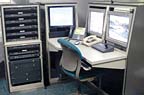
STEP 4 – The Change Out
The actual process of replacing each VCR/ multiplexer combination with a DVR and reconnecting the cameras required four technicians for about five days. Working on a DVR-by-DVR basis, the technicians would take one VCR and multiplexer out totally, put the DVR in the rack where the VCR had been and plug the 16 cameras back in. The technicians would then make sure the DVR could connect to the network and was recording properly. They also made any necessary programming changes using a laptop. Although that task could have been accomplished directly through the DVR, Allen says it’s easier to use a laptop because it has a QWERTY keypad, enabling simpler input of titles and other data.
Another concern was the hospital’s access control system. Although the two systems were not formally integrated, an important task was to ensure that the timer for each DVR was set for the identical time as the access control system to help in locating video images to match specific access control events.
Looking for quick answers on security topics? Try Ask SDM, our new smart AI search tool. Ask SDM →
STEP 5 – Wrapping up
Once the installation was completed, a representative from the hospital’s security department reviewed each camera and technicians made any changes that he wanted, such as changing the title of a camera. Technicians also reviewed basics of system operation with hospital security personnel. About three days later, a trainer from Tech Systems visited the hospital to provide more detailed training on system operation.
The hospital also has plans now to add DVRs to each of several urgent care centers in the area and to connect them to the network. Because the video surveillance system is becoming increasingly complex, another goal is to create a subnet for it so that IT can isolate the subnet’s operation from the hospital’s computer network. Also on the hospital’s wish list is to integrate the video system with the access control system.
Northeastern High-rise Office Complex
Engineered Security Systems of Towaco, N.J., had a unique challenge in upgrading the video system for a northeastern high-rise office complex. The four-tower complex, which originally had a single property manager, had been sold to three separate property managers – and one of them wanted its own separate system.Engineered Security, which had not installed the original system, got the job of splitting the system into two, one of which would be shared by two of the management companies. The old system had been VCR-based, but both new systems were to be networked DVR-based systems. The management company that wanted its own system was to retain the existing security center where the VCRs were located. The other two management companies were to get a brand new security center in a different tower, but would continue to use some of the existing cameras installed throughout the complex.
Each of the security centers was to have one or two DVRs controlling approximately 30 cameras, along with a personal computer running the client software for the video system. Each system also would have a guard station, equipped with a personal computer running video system software.
Because the original system was approximately 15 years old, Engineered Security was not confident in the quality of existing cabling and therefore wanted to install new cable throughout.
STEP 1 – Installation planning
Engineered Security Systems’ first task was to survey the site and plan the system. To assist in this process, CAD CAM drawings were created showing where the different types of cabling would go – Category 5 for the Ethernet network that Engineered Security would build, coax for the fixed cameras and two-pair twisted shielded pair for the pan-tilt-zoom cameras. The CAD CAM drawings also showed the location of each camera, including those that would be retained from the old system and any new ones that would be added. This planning process took about one month.
STEP 2 – Cabling
Installing the new cabling was the next step. This was carefully planned so that, where multiple types of cable had to be run to the same location, they were all pulled simultaneously. A particular challenge was how to connect the new security center to cameras located in some of the other towers. This required running cabling the length of two city blocks across a pedestrian bridge over a highway.“The only concern with distance was the communication cables for the pan-tilt-zoom cameras,†says Scott Guillemin, national project manager for Engineered Security Systems. After checking with the camera manufacturer, technicians learned that they could solve the problem by running heavier gauge wire than what was normally specified.
Cabling took about one more month, with anywhere from two to six technicians working on it at any given time.
STEP 3 – The change out
To help ensure a smooth transition, an Engineered Security technician programmed the DVR for each system in advance. The DVR was placed in its permanent location and, one-by-one, each camera was unplugged from the old VCR/ matrix system and plugged into the DVR. Two technicians handled this. One took care of the connections while the other viewed the images from each camera as the camera was turned up on a monitor. A member of the property manager’s security staff also reviewed the images.
“The only down time was when we swapped out each camera, and that was about one hour per camera,†Guillemin notes.

STEP 4 – Setting up the Ethernet network
The Ethernet network was installed after the DVR was already functioning as a stand-alone unit. That network included a router installed in the security center, the DVRs and two computers – one at the security center and one at the guard station. The network was turned up in one day, with one technician working in the security center and the other in the guard station.
The final step was to install client software on each computer connected to the video system.
STEP 5 – The future
Since the installation, Engineered Security has returned to the office complex several times to upgrade some of the older cameras to newer ones. The clients replace them as budget allows.Eventually the clients also would like to integrate the access control systems with the video systems.
Looking for a reprint of this article?
From high-res PDFs to custom plaques, order your copy today!


