FIELD GUIDE TO MONITORING: Alarm signaling & monitoring: technology overview
Digital Communication Systems
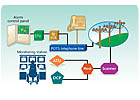
These systems are not connected directly to the monitoring station. Instead, they use a telephone line that is already installed for the user’s telephone service. When an alarm occurs, the digital communicator “seizes†the user’s telephone line, dials the telephone number for the digital communicator receiver installed in the monitoring station, and when answered by the receiver sends a data transmission to the receiver to report the location of the user and the type of alarm. Because the telephone line is not completely supervised, digital systems are considered less secure than systems that employ a constant supervision of the transmission path.To understand digital communication signals, you must first know the type of equipment used and how it works. There are two main components used in digital communication. Let’s refer to them as the user equipment and the monitoring company’s equipment.
USER EQUIPMENT: The user, who may be a homeowner or a commercial establishment, usually has a system that consists of various types or zones of protection. Zones mean that the protected premises is broken down into various sections for custom needs and ease of troubleshooting in the event of an area not secured.
These zones are wired into a control panel which is operated by the user. Various types of numeric or alphanumeric displays show the condition of the system and protected zones. This control panel is usually turned on or off (armed or disarmed) by a keypad or keyswitch device. Another component of the user equipment is the digital communicator, which is usually part of the control panel. This device receives information from the control and translates this information into a format capable of transmitting on normal telephone lines.
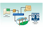
MONITORING COMPANY EQUIPMENT: The alarm signals that are sent by the user’s digital communicator are received by the monitoring station using a device called a digital receiver. Most digital receivers accommodate multiple standard telephone lines, which are attached to independent line cards. These line cards process data transmissions from digital communicators simultaneously and display them on their display panel and also send them to an automation computer and possibly a local printer.
To reduce the possibility of busy signals the telephone lines connected to the receiver are often configured in a circular hunt so that if one line is busy communicating with a digital communicator and a second communicator calls the same number, then it will be connected automatically to the next available telephone line.
OPERATION: When the digital communicator goes into alarm or a supervisory signal needs to be sent to the central office, the digital communicator seizes the telephone line and waits a predetermined amount of time for dial tone. If dial tone is detected, the communicator proceeds to dial in rotary or Touch Tone, depending on the programming or capabilities of the digital communicator. If dial tone is not detected in this short period of time, the communicator will hang up and try again.
This sequence is usually repeated a number of times, depending on features or programming of the digital communicator. When the digital receiver’s line card detects the line ringing, it picks up the line, usually after the first or second ring. Sometimes if the situation arises where the line card is busy with another communicator, the digital communicator hangs up and tries again. In some cases, a second number is called going to another line card on the digital receiver. Most digital communicators will make at least 10 attempts to reach a receiver’s line card.
Once the line card senses the ring signal, which is approximately 20 Hertz, the receiver picks up the ringing telephone line, pauses, then delivers a handshake frequency, such as 1400 Hertz, 2300 Hertz, or some other signal. This handshake tells the digital communicator that it has reached the receiver. Upon receipt of the appropriate handshake, the digital communicator will proceed with the data transmission. Assuming the receiver verifies the data transmission as a valid format, the receiver will deliver a kiss-off tone. This causes the communicator to shut down, unless more data is available, in which case further data transmissions and kiss-offs occur.
After final kiss-off, the receiver will release the telephone line and process the data to its display panel, automation computer, and local printer. The digital communicator also will release the telephone line it seized, until the need arises for another transmission to be sent the digital receiver.

Radio Transmission Systems
Radio transmission systems use a specially assigned radio frequency and a complex network of computers and transmitters to transmit alarm signals from the user’s premises to the monitoring station. The system can take many forms, such as a private radio network, a shared public wireless network, or even the cellular network. Some of these networks require that the monitoring company obtain a license from the FCC, while others allow the monitoring company to utilize the existing FCC licensed structure.Cellular-based systems may operate as zone input devices, where inputs of the cellular are activated by triggers from the control panel, or they may provide full data transmission by converting the data that the digital dialer would normally send over a standard telephone to a digital signal, which is then transmitted over the cellular network.
These systems have the advantage of providing the monitoring station with all of the information that the digital communicator could send over the telephone line. The amount of information that zone input devices transmit is limited by the number of input zones of the transmitter and the number of outputs that the control can provide.
USER RADIO TRANSMITTERS: There are two basic types of remote transmitters used to provide the links between the user and the monitoring station. The first type provides one-way communication, sending status messages of its zone inputs. The one-way transmitter may be capable of activation upon sensing voltage or the removal of voltage from any of its zone inputs. The system sends both premises event messages, signaling zone-fault situations, and status messages which notify the monitoring station of system status or operational fitness.
The second type of radio transmitter used provides a two-way radio link between the user and the monitoring station. It is a high-security unit operating in a polled/response mode, in addition to including all of the features of a one-way transmitter. This constant supervision of the communication path provides the two-way radio with a very high level of security.
Both types of transmitters are interfaced with a control panel, usually a digital communicator, but also can be used with any other type of control capable of supplying outputs to trigger the radio transmitter’s zone inputs.
Derived Channel
Derived channel is a technology that like a digital communicator, uses the user’s existing telephone line to transport alarm and other critical event information, without interfering with normal voice service. The big difference is that derived channel also provides a constant supervision of the communication path to ensure signals are received. Although not widely available, derived channel can provide a high level of protection at a lower cost than two-way radio systems. There are four main components used in derived channel.SUBSCRIBER TERMINAL UNIT (STU): The STU is located at the user’s premises mounted inside the cabinet of a control or in its own enclosure. Depending on the type and manufacture of the STU used, there can be multiple input zones used to monitor detection devices which may include intrusion or motion detectors, heat or smoke detectors, and medical or panic buttons.
SCANNER: The scanner is a communications controller/multiplexer located within the telephone company’s central office. The derived channel network consists of many scanners geographically located throughout the monitoring station area. The scanner periodically polls or interrogates the STUs for current alarm status.
HOST PROCESSOR SYSTEM: This portion of the network, which is sometimes called host computer or message switch, consists of a pair of computers located within the telephone company. The host communicates with all scanners connected to the network. The function of the host is to route all messages from the scanners to the designated alarm dealers through its disk resident database, while also logging all transactions. All scanners and alarm dealers are connected to the host via two data circuits. All main components throughout the system are installed with redundant backups.
ALARM COMPANY (AGENCY) EQUIPMENT: Although there are many different configurations available using various manufacturers’ equipment, this is a brief description of the components:
- Agency Terminal Unit (ATU): The ATU receives messages from the host computer by way of a modem connected to a dedicated telephone line. The ATU translates the binary poll/response message protocol (format) used by the STU into readable messages displayed on an agency computer terminal. These messages scroll across the terminal screen in easy-to-read English, as soon as the data is received from the host computer. The ATU also allows the monitoring station operators to send commands to the individual STUs and messages to the host supervisory terminal, if needed.
- Derived Channel Processor (DCP): The DCP panel receives the same messages from the host computer as the ATU, but receives them via its own modem and dedicated telephone line. The function of the DCP is to receive the alarm messages from the telephone company’s host computer and translate them into a format that is compatible with the monitoring company’s automation system for signal processing. The DCP processor may have warning indicators and audible to indicate the system failures, such as the automated computer has failed to respond to signals sent by the DCP processor; a communication failure between the DCP modem and the telephone company’s host computer; a message has been sent by the supervisor (telephone company) and can be retrieved at the ATU terminal. The DCP panel also includes an A/B toggle switch which can be used to swap telephone lines with the ATU, in case of failure.

Internet Monitoring
The proliferation of Internet use has presented a new avenue for alarm monitoring. This medium is widely available and affordable and can provide a high level of security across the street or around the world. The same technology used for monitoring over the Internet also can be used to monitor multiple locations for users that have their own data network. Transmitting emergency signals over the Internet is very fast and can provide a level of supervision that once required dedicated leased telephone lines.
VoIP
Voice over Internet Protocol (VoIP) is a relatively new technology that is making inroads in the residential and even the commercial markets. It utilizes the Internet to provide telephone communications, replacing traditional Plain Old Telephone Service (POTS) as a means of communication. The primary reason for the surge in VoIP usage is that it can provide telephone service at a much lower cost to the user and provide telephone service that is not determined by a physical location but rather anywhere a connection to the Internet can be achieved.From a monitoring perspective VoIP works the same as a traditional digital communicator with the addition of devices that allow connection to the Internet and that all signals are converted from analog to digital and then sent over the Internet. Some dealers have reported some problems when users changed their telephone service to a VoIP provider, and it is a good idea to verify that any systems that use VoIP are tested to ensure proper operation. Today, however, there is equipment being marketed that was specifically designed to allow emergency monitoring using VoIP, which can overcome the problems that have affected the traditional digital communicator; some also have the option to include a traditional POTS line for backup.
Automation Computers
Monitoring security systems requires a great deal of accurate information and highly trained qualified operators. To maximize the operator’s ability to react to emergency signals, computerized automation systems are employed in the monitoring office to handle routine events such as openings, closings, and test timer signals. These computers provide exception-only events, such as burglar, fire, or medical to the operator along with all of the information that is necessary to properly dispatch the appropriate agencies and notify the designated parties.This process starts when the user completes an emergency notification sheet that lists the address of the premises, names and telephone numbers of all parties that are authorized to use the system and the telephone numbers of the local police, fire, and medical personnel. This information is added to the data provided by the installer showing what type of equipment is connected to each zone, along with any required permit information.
When an alarm is received, the operator is automatically given all of the information necessary to handle the signal and the automation system will automatically record what actions the operator took and when they were taken. This provides an audit trail that is stored and can be printed whenever necessary.
These automation systems are generally configured in a redundant fashion with standby power systems to provide uninterrupted operation in the event of an equipment or power failure. The manager of the monitoring station also may make backups of the database for on-site and off-site storage in the event of a catastrophic emergency.
Side bar: Benefits of Internet Monitoring
Using the Internet to monitor emergency signals offers many advantages over other communications technologies, such as low cost, high-speed data transmission, and end-to-end supervision of the communication path. Cost savings can be achieved by using the existing full-time Internet connection that already may be in place at the protected premises. The same connection that the customer already uses to surf the Internet also can be used to monitor the security system, in many cases without the need for a fixed IP address.Internet monitoring also eliminates busy signals, costly telephone-line, long-distance, and toll-free telephone charges. The transmission time to send signals using a digital communicator can take almost a minute, while the same information can be sent over the Internet in well under a second, providing the monitoring station with critical information virtually immediately after an event occurs.
It is even possible to use the Internet to remotely program and troubleshoot the control using remote programming software. Program downloads that can take 20 minutes using traditional telephone service can be accomplished in just minutes over the Internet.
Side bar: Internet Transmission Speeds
There are many options available for full-time Internet connections, such as ISDN, DSL, cable, satellite, and T1 lines. Which type you use depends upon availability, cost, and data-transmission requirements.Because the transmission of emergency signals typically requires less than 100 bytes of data, bandwidth is generally not an issue unless you are planning on using the Internet to send video signals. The following table presents general guidelines for the relative throughput speed of the most common Internet connections available.
- Type of connection
- Bits per second
- 2-channel ISDN
- 128k
- DSL1
- 512k
- Cable2
- 1m
- Satellite
- 500k
- T1
- 1.5m
Notes:
- The speed of a DSL line is dependent upon the type of service ordered.
- Cable speed can vary due to shared usage.
Side bar: VoIP Issues
While VoIP may be very inviting to the security system user due to its lower cost, it can cause potential problems to a company that is monitoring the security system. This is not to say that security systems will not work with VoIP, but rather that there are some additional concerns that must be considered when a user switches to a VoIP-based telephone system.The first and most obvious issue is standby power. The security system has rechargeable batteries to provide power in the event of an outage, but do the required VoIP components such as the modem and telephone adaptor also have this vital capability? Typical network devices are not designed with internal standby batteries because, if desired, they are connected to an uninterruptible power supply (UPS), but some VoIP providers offer standby power additions as an option. Network uptime is also of concern when using the network to transport emergency signals. Having a Web page not be available for a brief period of time may be annoying when surfing the Web, but when an alarm occurs, that lack of connection can be disastrous. Finally, distortion and latency also can cause problems for some digital formats when connected to a VoIP line. These potential troubles are a result of the conversion from analog to digital that occurs with VoIP lines and the delays that can happen as the data packets are assembled and shipped over the Internet.
Looking for a reprint of this article?
From high-res PDFs to custom plaques, order your copy today!


