6 Key Questions About Video Power
The importance of a strong foundation to the success of every security installation simply cannot be understated.
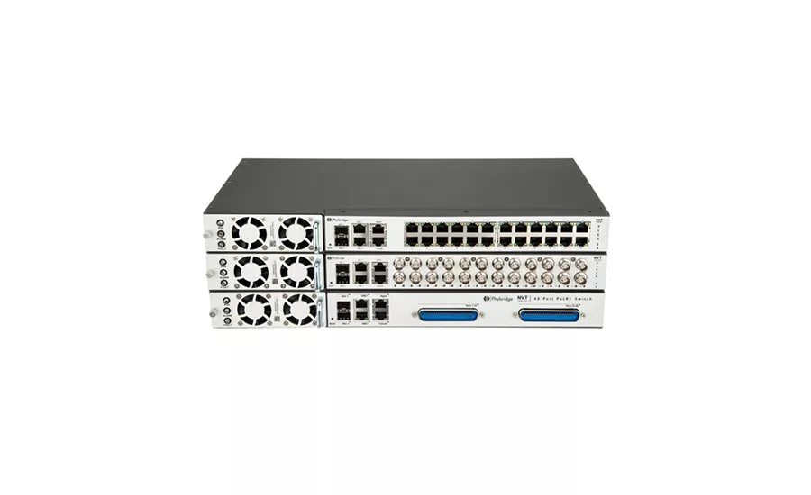
Available technologies such as the CHARIoT series from NVT Phybridge have eased the ability to use existing coax cabling for upgrading video systems without sacrificing several of the benefits Ethernet-based systems have to offer, such as PoE. Photo courtesy of NVT Phybridge.
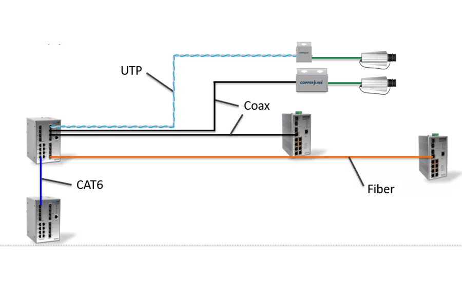
Naturally, every cable type brings its own distance limitations, which vary widely from medium to medium, but there are a number of solutions, such as ComNet’s CopperLine SFP, that allow integrators to extend those distances over copper, fiber and UTP. Photo courtesy of ComNet.
At the foundation of every system is the infrastructure that provides the power and a means of transporting data from an end point to a centralized headend. In designing or upgrading a system from analog to IP, there are many factors that go into choosing the best technologies for these vital functions. To help guide integrators towards the most appropriate power and transmission solutions, SDM posed six common questions to several industry experts, whose answers are found within this article: John Croce, CEO, NVT Phybridge, Oakville, Ontario; Frank “Skip” Haight, vice president of marketing, Communication Networks (ComNet), Danbury, Conn.; John Nave, design center engineer, ComNet; Ronnie Pennington, national sales manager, Altronix, Brooklyn, N.Y.; and Chad Szekeres, national sales manager, Nitek, Rolling Meadows, Ill.
SDM: All things being equal, what cable type is most preferable and why?
Haight: It’s a tough call declaring what medium is the best and therefore most preferable. The primary methods of transporting Ethernet/IP video are over copper; CAT 5e or 6 UTP cables and coax, fiber optic or wireless. Each has its benefits, advantages and disadvantages depending on the requirements of the installation. CAT5e/6 are most commonly used, but fiber optic still has the bandwidth/distance/immunity advantage. Copper is still important and with modern transmission products, distances can be extended significantly and PoE can be utilized over those greater distances.
Fiber optic transmission will continue to be the standard for bandwidth and distance. For Gigabit speeds and now with 10 Gigabit throughputs becoming necessary, single-mode fiber becomes the only real solution for any reasonable distance. Looking forward, I don’t believe there will be a new transmission medium invented, but what can be done over these different media is certainly going to advance: greater PoE distances and power over copper media; greater distances with less chance of interference from wireless; and greater bandwidth over distance with fiber. All have their benefits, and integrators should not have any concerns about using one or all to solve transmission challenges they may face.
Pennington: In general, I would have to say that with current IP technology, Ethernet cabling is most often the preferred choice because it has the capability to transmit both power and data. Considering cabling and installation costs, Ethernet cable is also very cost competitive when compared to fiber or coaxial cable. It is easy to pull and in many cases today is increasingly available at most installations constructed or renovated in recent years.
SDM: That said, which cable type is most prevalent in today’s video systems?
Croce: For analog cameras it would be coax. The migration to IP creates some challenges in that the rip-and-replace of this cable to support IP end points can be costly, disruptive and risky for business. Also, many of the runs go beyond the 300 ft. reach limitations of standard Ethernet. New Long Reach PoE over coax switch innovations have been introduced to eliminate the need to rip and replace and transform the existing coax into a robust PoE backbone ideal for IP cameras.
Looking for quick answers on security topics? Try Ask SDM, our new smart AI search tool. Ask SDM →
Haight: In older traditional analog CCTV systems, I’m sure the most prevalent is still coax. But with the migration to Ethernet, UTP cables have become far more prevalent. Most IP devices, have a standard RJ45 connector that utilizes Cat5e/6 cables. From there, depending on where, how far and what they connect to, some type of media converter is used. It can be converting that Ethernet electrical signal to light (fiber optic), to radio (wireless), or extending the distance electrically (over coax or UTP). Many of today’s Ethernet switches feature SFP sockets. These sockets have the capability of accepting almost any type of fiber optic connector or fiber type (multimode/single-mode), or UTP/Cat5e/6, or distance extending UTP and coax. Connecting to a wireless product is generally done using a UTP cable.
Pennington: Most new installations are currently using Cat6 cable so that they get all the benefits of current technology while maximizing future upgrade potential.
SDM: What distance limitations exist with the various forms of video cabling and how, if at all, can they be overcome?
Croce: Standard PoE Ethernet reach is approximately 300 ft. and requires CAT5 or better cable. However, switch innovations have been introduced to leverage different cable types and go up to six times further than standard PoE switches.
Haight: Looking at the main types of transmission media, copper, fiber optic and wireless, each has a realistic maximum safe transmission distance. Fiber optic transmission distances have the generally accepted max distance. Many IP devices can use SFP (small form factor pluggable) modules as the optical connector. The advantage that comes with using these devices is that connector and distance can be chosen to satisfy the requirements of the application.
Copper cabling, be it coax or UTP, have distance restricted by resistance. One of the electrical properties associated with copper wire is resistance. The electrical resistance of an electrical conductor is the opposition to the passage of an electric current through that conductor. Without overcomplicating this discussion, the greater the physical distance, the greater the difference is between the voltage applied at one end and received at the other end. The point of this is that often, given the transmission distances of the cable, many times the power supplying equipment cannot pass through enough power to operate the equipment at the remote end. That becomes the limiting factor for copper-based transmission media.
SDM: What are some of the reasons behind video loss and how can integrators avoid them?
Croce: Loss of power supporting the end point: Look to build a PoE backbone with PoE redundancy strategies. A few managed PoE switches have this capability. Another cause is poor cable connections. Test the cable before or use managed switches that provide information about quality of connection and packet loss and link down events.
Nave: Video systems can be relatively simple or quite complex, comprised of cameras and devices for transmission, encoding/decoding, signal conditioning, monitoring, control, multiplexing, and recording. Even well-designed video systems can experience failure. As with any electronic communications system, almost all reasons for video loss can be grouped into eight general categories:
- user error;
- intentional or malicious actions;
- equipment failure;
- cabling issues;
- power and grounding issues;
- electro-magnetic interference (EMI);
- compatibility issues; and
- improper system design.
(An in-depth look at each of these categories can be found below.)
SDM: What are the pros and cons of using existing coax for IP-based cameras and other video equipment?
Haight: In the past, standard Cat5e/UTP cables were limited to 100 meters for most Ethernet transmission. There are many available product lines that act as distance-extending devices that push distances out to over 600 meters for UTP and coax for 100MBPS data rates. If there is any downside to coax/UTP for IP transmission it is that some cable is now so old, possible signal degradation may occur.
Pennington: On the positive side, using existing coax cable for an otherwise new IP system can save the cost of purchasing and installing new cable, can carry both power and data, is easy to connect with existing and new devices, and minimizes disruption to business operations during installation.
On the negative side, the use of existing cable also brings potential problems and costs including time, effort and expense for technicians to ascertain what cabling is available and how it can be adapted to meet the new system’s needs; inspection of all cable and connections to ensure it is in good working order; and projecting expected life of existing cable versus new cable. When these considerations are tallied, the actual savings may not be as large as anticipated.
Szekeres: There are several pros of using existing coaxial cable for IP-based camera systems. One of the more obvious is a material and labor savings to the contractor. The majority of legacy analog cameras were originally installed using RG59/U coaxial cabling, which was commonly installed as a collection home run cables. For example, Nitek’s Etherstretch solution allows IP communication and PoE+ over existing coaxial cabling.
Besides reducing installation cost there are several challenges this technology helps to overcome. Many contractors consider this technology to minimize or eliminate disruption to daily operations during installations. These devices are plug-and-play, requiring no configuration or set up and are completely transparent to the network. Simple troubleshooting is accomplished by monitoring power and data communications using LEDs on both the transmitters and receivers.
SDM: What new technologies are there in video connectivity and/or power and what are their benefits for integrators?
Haight: One of the major concerns integrators have is unauthorized access to their security network — cyber security. Access to a security network can be as easy as unplugging a network device such as an edge IP camera, connecting a computer and hacking into a network, possibly bringing down all the other cameras and systems, as well as the access control system. Our company has introduced Port Guardian, which detects the disconnection and physically locks out the port. It automatically sends SNMP notification to the headend or admin — notifying of the port that has been disconnected. Admins can then reset after threat is resolved. This simple feature can save a company from an unauthorized access.
Pennington: One exciting new technology development is the ability to locally or remotely monitor, control and report on power. For example, PoE can be scheduled to automate infrared illuminators, rather than leave them on at all times, wasting power and shortening their useful life. Another useful example is the ability to remotely “pulse” power to reboot a wireless node. These tasks are much more difficult if the devices were hardwired or powered locally.
The Continuing Evolution of PoE
Most equipment manufacturers’ offerings now include models that offer PoE capability, which has essentially become the primary means of powering video systems today. This is largely due to the ability to provide power and transmission for any IP device over a single cable and eliminating the need to install separate power cables, which significantly reduces costs.
As new IP-powered devices are developed, network power and transmission manufacturers continue to design and develop products that supply the increased power requirements and meet some of the challenges these devices pose, says Skip Haight of ComNet.
“The challenge now is the ever-increasing requirement for more delivered power. The first standard, IEE 802.3af was for 15 watts, IEEE802.3at or PoE+ was for 30 watts and now IEEE802.3bt 4PPoE or UPOE is for 60 watts,” Haight says. “As these PDs require more power for the use of PTZ and heaters, more power must be supplied.”
The 8 Most Common Causes of Video Loss & How To Avoid Them
According to John Nave, design center engineer for Danbury, Conn.-based Communication Networks (ComNet), there are eight general categories into which nearly every reason for video loss can be grouped: user error, intentional or malicious actions, equipment failure, cabling issues, power and grounding issues, electromagnetic interference (EMI), compatibility issues and improper system design.
To help integrators avoid these common causes and ensure the most reliable video systems for their customers, Nave offers the following solutions.
User error: While it may not eliminate the issue, a well-designed system along with well-written user instructions and good training can minimize user error. Instructions should include easy-to-understand parameters including system limitations, capacities and capabilities.
Intentional or malicious actions: Video systems are mainly used for security and surveillance or for automation and process control. While use of video systems for automation and process control is generally welcomed, electronic security and surveillance may not always be viewed in the same way. Because these systems are almost always performing functions that had been or that could have been performed by people, they may not always be as welcomed by labor unions or workers whose jobs may be impacted. Tamper switches and enclosures or areas with access control and secondary monitoring systems may need to be considered depending on the level of concern.
Equipment failure: Any device — whether active or passive — can and likely will fail at some time in its useful lifetime. This can be caused by a component failure, influences in the environment (such as temperature extremes, excessive moisture, dirty power, accidental contact with high voltage including lightning, etc.) or due to malicious activity.
Selecting high-quality, well-designed product is the best defense against premature component failure. Whenever possible, specify products from a recognized company with a strong track record of service, support and reliability. Proper system design, discussed below, can help minimize losses from environmental influences.
Cabling issues: At least in part, every electronic communications system uses copper-based and/or optical fiber-based cabling. Even wireless systems use cables, if only to connect short distances between supporting devices. All cabling should be strictly specified as to pinout, composition, number of strands or conductors, shielding or lack of a metallic shield, maximum allowable lengths, etc. Defining the proper environmental rating of the jacket warrants the most attention.
Copper cabling or optical fiber cabling can be purchased as factory terminated and tested or it can be self-terminated and tested. Whether factory terminated or self-terminated, it is highly recommended that installers carry the proper cable test equipment to confirm cable parameters or to rule out cable issues.
Each and every optical fiber should be tested. Optical loss testing should be performed end-to-end and as optical loss is directional, should be performed in each direction at the wavelength(s) that will be used. For example, a good report would show the following four results when testing at 1310 nm and at 1550 nm. The losses in dB shown in the example below are for illustration only as they will vary depending on the actual fiber path. To cross-check results, use the following conservative parameters:
- Loss per 1,000 ft. of multimode fiber @ 850 nm = 1 dB
- Loss per 1,000 ft. of multimode fiber @ 1,300 nm = 0.5 dB
- Loss per 1,000 ft. of single-mode fiber @ 1,310 nm = 0.2 dB
- Loss per 1,000 ft. of single-mode fiber @ 1,550 nm = 0.1 dB
- Loss per mated connector pair = 0.75 dB
For example, testing a single-mode fiber at 4,000 ft. in length with one connector-to-connector coupling in the fiber path:
Cable 1, fiber 1:
- Calculated end-to-end loss @ 1,310 nm reading should be 0.2 dB x 4 + 0.75 dB = 1.6 dB, max.
- Calculated end-to-end loss @ 1,550 nm reading should be 0.1 dB x 4 + 0.75 dB = 1.2 dB, max.
Testing at 1,310 nm:
- Cable 1, fiber 1. From Point “A” to Point “B”. End-to-end optical loss = 1.4 dB @ 1310 nm.
- Cable 1, fiber 1. From Point “B” to Point “A”. End-to-end optical loss = 1.5 dB @ 1310 nm.
Testing the same fiber at 1,550 nm:
- Cable 1, fiber 1. From Point “A” to Point “B”. End-to-end optical loss = 1.0 dB @ 1550 nm.
- Cable 1, fiber 1. From Point “B” to Point “A”. End-to-end optical loss = 1.2 dB @ 1550 nm.
Continue on to Cable 1, fiber 2, etc.
Similar testing can be performed on copper-based cables to measure simple continuity, frequency response or to detect ground faults, for example.
Type and number of connection points should be specified, as well. Too many connection points can yield a system that is unreliable, intermittent or unusable. For example, an optical fiber path should not contain more than two connector-to-connector couplings. The air gaps introduced by such couplings become the issue. Mechanical splices or fusion splices eliminate the air gap and should be used as alternatives. Similar parameters exist for copper-based systems as well.
Power and grounding issues: Frequently overlooked, possibly because of perceived simplicity, providing proper power and proper grounding to an electronic communication system deserves much attention during system design or troubleshooting. Power problems can result from improper power (the wrong type or level of power), dirty power (spikes, noise, etc.) or unreliable access to a constant source of power. Grounding issues can result in potentially damaging ground loops; lack of a proper signal ground can prevent operation altogether.
Any electronic device wants to consume a constant amount of power. If the proper amount of voltage is not available for a device, it will respond by altering the amount of current that it will draw in an attempt to maintain constant power consumption. It goes without saying that providing too much voltage to a device will damage it. Similarly, and usually not quite as dramatically, providing too little voltage can damage an electronic device as well.
A device receiving too little voltage will respond by attempting to draw more current if it is available. Depending on the severity of the deficiency, this could result in damage to the electronic device over the long term. Use of an uninterruptable power supply (UPS) often misleads users to believe that their electronic devices are being properly powered and protected. Not infrequently, the opposite can be true. A well-designed UPS will provide the proper amount of voltage in the form of a smooth AC sinusoid. A UPS that allows an under-voltage condition and/or AC sinusoids that are not clean can actually allow damage to the connected electronic device(s) to occur in the long term.
Grounding issues are simple to design on paper but can be quite complex to implement or troubleshoot. Electronic devices use a ground reference for power as well as for signal. The ground also serves as a means of protecting these devices by draining noise or potentially damaging current away from the devices. Protective grounds should ideally have a zero Ohm short to a solid earth ground achieved by a proper copper cable. Power and signal ground connections could be more complicated because they can be needed in more than one location in an electronic communications system. The danger is that ground references at physically diverse locations may differ and whenever the ground potential is different between any two locations, current will flow. This current is called a ground loop and depending on the severity, can cause communications problems, prevent communications altogether or damage the equipment. Follow grounding code and best practices and use ground loop isolators as needed.
Electromagnetic interference (EMI): Sources of EMI may be difficult to control, especially if the source is from a neighboring location not directly controlled or owned by the video system user. For example, an adjacent property may contain a microwave communication system, a RADAR system or some other source of high-level EMI. A business can use a microwave system as a back up to their primary Internet link, and a nearby airport or shipping port will use RADAR. Hospitals and schools could have equipment that generates high levels of EMI. Physical separation, shielding and use of ferrite rings in power and signal cabling are the best defenses from EMI.
Compatibility issues: When electronic communications systems are designed, it is typical for system components to be sourced from multiple manufacturers. When mixing devices from different sources that must communicate with each other, proper selection and integration of components warrants attention to detail. In addition to making sure that signal types, levels and impedances match, compliance with standards must be considered.
For example, PoE is almost ubiquitous and while standards do exist, not all PoE devices comply with the standards. For PoE, the IEEE has created the 802.3af (prior to 2009) and the newer 802.3at standard (since 2009) that defines power levels and signaling between PoE devices. The device that produces the PoE — the Power Sourcing Equipment (PSE) — and the device that requests and ultimately will use the PoE — the Powered Device (PD) — must both comply with the same IEEE PoE standards.
Improper system design: Probably the single greatest impact on system function and long-term reliability is proper system design. Failures, errors or omissions during system design — unless caught before being implemented — can have consequences that range from mild inconvenience to system failure and economic losses. Most issues have been covered in the items previously discussed but should be addressed during system design. In summary, they include controlling access to sensitive system components to minimize the chance of malicious activity; selecting good quality, reliable sources for equipment and cabling; specifying proper testing for cables and equipment; considering power, grounding, and potential EMI issues; confirming compatibility and proper integration between system components; confirming compliance with industry standards; and always specifying best practices.
Looking for a reprint of this article?
From high-res PDFs to custom plaques, order your copy today!


