A Guided Tour of Ethernet Cameras

Many of today’s electronic security systems are designed to operate on a communications/computer network. SDM NetWorkings can help you understand both the intricacies of communication networks, as well as how security systems fit into the networked world. It features excerpts from the “Technician’s Guide to Networking for Security Systems,†a book written by SDM’s contributing technology editor, David Engebretson. (See end of article for ordering information.)
The manufacturers of electronic security products are responding to the exciting opportunities of networking by producing many new cameras with Ethernet connection capability. In this installment a typical network-enabled camera will be examined, concentrating on those aspects of networking that are common to most network cameras and may require manipulation by the security installer to achieve communications.
The Ethernet camera used for this example is a Panasonic MV-NM100, a compact and powerful device with many attractive features.
Initial Programming
The two primary methods used to connect to an Ethernet camera are either to use the default IP address, or to use the manufacturer’s setup software, which will provide a MAC search function.First a laptop or PC must be connected to the camera via a Cat 5 UTP jumper cable. If the camera is directly connected to the computer, a crossover cable must be used, whereas if the camera and computer are both connected to a gateway router, hub, or switch, the jumper used is a standard patch cable.
For initial programming, it is generally easier to use a directly connected computer, rather than going through the network. For this example, the IP camera is directly connected using a crossover cable.
Every new IP camera is shipped with a pre-programmed default IP address from the factory. To reach the camera’s programming options, first review the camera’s instructions and locate the default IP address. The default IP address for the MV-NM100 on initial power up is 192.168.0.10. After connecting the programming PC or laptop to the camera and connecting power to the MV-NM100, reset the “Local Area Connection†IP in the computer to an address on the same network as the camera. For this camera, the computer should be programmed to an unused address in this range, 192.168.0. (1-255). A simple address to use would be 192.168.0.1.
Open an Internet browser such as Internet Explorer, and type in http:// 192.168.0.10
The camera’s user name/password screen should appear. Use the proper entries obtained from the instruction manual. The control and programming fields of the camera are now available for review and changes.
Connecting to the Camera Using MAC Search
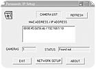
Camera vendors often supply installation software that provides a MAC search function for connecting to cameras and setting the camera’s IP address. In the case of the MV-NM100, after connecting the PC to the camera, inserting the installation disk will pop up this screen (top of next column):When the “Setup†button is clicked, the next screen appears. Manufacturers program pre-set MAC addresses into each IP camera or device. These are unique hardware identification codes; every individual device has a different MAC address. The installation software knows the range of MAC addresses used by that particular vendor, and will search out and display the related devices on the search screen.
Looking for quick answers on security topics? Try Ask SDM, our new smart AI search tool. Ask SDM →
In this case, a single camera has been located. Highlighting the MAC address and clicking “Network Setup†will open the next window, where the basic IP address information can be accessed and changed.
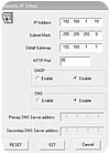
Notice in the next example (top of page 108) that the IP address of the camera is 192.168.1.10; this camera has already had its IP address changed to work with the Security Networking Institute’s LAN.
Either of these methods can be used to access this particular camera’s programming. Be aware that some Ethernet cameras only provide the default IP method of initial communication.
Security Technician Note: Active software firewalls will often block MAC search programs. If the MAC addresses don’t appear when searched, and the camera is powered and connected properly, turn off the software firewall and try again.
Programming Network Addressing
After using one of the two methods above, the camera is accessible for addressing and programming. The installer should be prepared at this point with the IP address that will be used by the camera, as well as a port selection if the camera is to be viewed from over the Internet.If using the MAC search function detailed above, it is a simple matter to change the IP address of the camera to its “permanent†setting. The camera illustrated in the diagram above is programmed for IP address 192.168.1.10, standard subnet mask, Default Gateway (the gateway router’s LAN IP) 192.168.1.1, and is set to Port 85. DHCP and DNS are disabled. The technician can make any changes, click “Set,†and the changes will be made.
If the IP address has been changed from one Class C network to another, such as from the camera’s default IP 192.168.0.10 to 192.168.1.10, the camera will disconnect from the programming PC once the change has been “Set.†This disconnection occurred because the camera and the programming PC are now addressed for different networks. Now to reach the camera, it will have to be properly connected to the client’s network, and accessed using an Internet browser, inputting the camera’s new/permanent IP address.
When connected to the camera using an Internet browser and the camera’s default IP address, the IP addressing screen can be accessed by clicking to the “Advanced Settings†and “Network†screen.
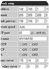
In the case of the MV-NM100, the following screen is displayed:
Here is where the technician can input the proper LAN IP address, subnet mask, and default gateway, which is the address of the gateway router to which the camera is connected.
Under these settings is a selection for “Network Speed.†As Ethernet has developed, there have been various subcategories of Ethernet, such as “Half Duplex†and “Full Duplex.†Normally selecting “Auto†allows the IP camera to negotiate the best transmission protocol to use in its communications with the router or switch to which it’s connected. This particular camera offers both 100 and 10 Mbps Ethernet, while many of the currently available network cameras only operate at 10 Mbps. As was mentioned previously, this can cause problems if switches, routers, or media converters that will be connected to the camera operate at 100 Mbps only.
The “HTTP Port†selection allows the technician to program camera access from the WAN or Internet onto a specific port. This product, like many IP network cameras, is shipped with the default port of “80,†which is the port typically used by the network for HTTP (Hyper Text Transfer Protocol) communications. HTTP connections require the host, in this case the camera, to connect to a viewing computer using a typical Web browser program, such as Internet Explorer.
The “Host Name†can be selected to provide another name by which the device can be accessed over the network. For a camera, this name might be North Lobby, West Stairwell, or some other name that gives information about the view that the camera is providing to the monitoring computer.
Shorthand for “Bootstrap Protocol,†this is a startup protocol that allows a diskless node, such as this camera, to determine its IP address and the address information for the gateway router to which it’s connected.
This setting allows the MV-NM100 to receive a Dynamic Host Control Protocol address from the gateway router. If this setting is turned on, the “Host Name†must be used to connect to the camera, as the IP address can periodically change.
Some larger networks will have their own internal DNS server, which resolves host names into their numeric IP addresses. If this particular camera is programmed for FTP image transfers and e-mail notifications, and if the FTP and e-mail servers are input as “Host names†in the “Alarms & Transmission†fields, DNS must be enabled, and the DNS server address input in the field below.
Once the proper settings have been input, clicking “Set†will apply any changes that have been made. If the settings are correct, the camera should now be accessible using a Web browser from another network computer, provided that the camera has been properly connected to the gateway router.

Other Network Settings
While initially accessing the camera and setting the basic IP address information can provide a network camera with connectivity to the LAN, there are other features available that can be set to provide specific functionality to the device being programmed.Time settings on IP cameras can be critical if the transmitted and stored images are to be used for evidentiary purposes. If the camera is connected to the Internet, a Network Time Protocol (NTP) server’s address can be programmed, which will automatically coordinate the time settings of the camera to the atomic clocks used to coordinate the time settings of Internet servers and devices. There are a number of different NTP Web sites available; generally this is a free service.
The MV-NM100 can be programmed to transmit e-mail notifications of alarm events, such as when motion is detected via the camera’s internal motion detection program, or when an external device such as a door contact or alarm system motion detector that has been wired to the camera’s external alarm input is activated.
In the programming fields above, the settings for the type of e-mail service, usually Simple Mail Transfer Protocol (SMTP) or Post Office Protocol version 3 (POP3) and Authentication can be obtained from the ISP.
Ethernet Camera Tour Review
The primary concern of the alarm technician is the proper programming of an Ethernet camera’s IP address and port number (if accessibility over the Internet is desired). Once the camera has been addressed and is reachable over the network, other settings such as video imaging issues, compression codecs, and image storage and transfer can be manipulated.Remember, the features or options of various cameras and other networked security devices can differ widely, as well as how common features are accessed or manipulated.
Links
Looking for a reprint of this article?
From high-res PDFs to custom plaques, order your copy today!