Planning an Installation
Fiber cable provides the following advantages for a video surveillance/access control system installation:
• Great Distance — Where coaxial cable (RG59, RG6) can only carry video signals up to 1,000 ft. without amplification, multimode fiber optic cable easily can carry video signals up to four miles from the camera to the monitor without additional amplifiers. Singlemode fiber can carry the same camera signal 20 miles or more. There may be applications where only fiber optics can carry the signals needed for the distance required.
• Multiplexing — Fiber strands have much greater bandwidth potential than their copper cousins, so many camera signals can be carried on a single fiber strand. By multiplexing the signals, multiple cameras can be connected to one fiber, while multiple pan/tilt/zoom controls can flow back to the camera location on the same strand of glass that carries the video signals. Bi-directionality gives great flexibility to a fiber optic camera or access control application.
• EMI and RFI Rejection — Being glass and carrying no electrical impulses, fiber optic strands are totally immune to electromagnetic or radio frequency interference. Many copper-based systems suffer from excessive noise generated by factory machinery, air conditioners, and generators. An industrial environment may require fiber cabling for your system, even if the distance from head end to camera is within the normal limits of copper cabling.
• Elimination of Grounding Problems — Proper installation of electrical systems requires grounding to protect against surges and transient voltages. When a differential exists between the grounds at each end of a copper video installation, “hum†bars may appear on the monitor, and these can be difficult to eliminate. With fiber there is no possibility of different grounds, as there is no current-carrying connection between the cameras and the head end.
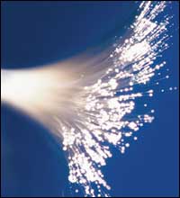
• Cable Size and Weight — Fiber cable is much smaller than coax cables and is easier to install due to its small diameter and light weight. Consider an example of an eight-camera installation on one floor of a building, with the monitors 500 ft. away. Eight RG59 coax cables would require at least a 3-in. conduit. A single multimode fiber cable has an outside diameter of 3 millimeters (see photo below), and can be easily fitted into a ½-in. conduit. When conduit costs are included, fiber optic cable may be less expensive to install than coax.
One common truth about security systems is that the end user will want to expand the system in the future. By using fiber, the installation company achieves a straightforward upgrade path for adding cameras, access readers, or control points. Because the bandwidth of fiber is so broad, you can easily upgrade a system by installing new transceivers that will carry the new quantity of signals needed. No new cabling installation would be necessary.
Looking for quick answers on security topics? Try Ask SDM, our new smart AI search tool. Ask SDM →
Installations that combine fiber and copper are truly the practical approach to achieving the best installation at the lowest cost. Use fiber where it is needed, installed to central points at the monitoring/head end location and at a central point for the cameras, readers, and access points. Use appropriate coax or copper cabling from the fiber/copper transceiver or converter to the cameras and readers. Most fiber devices will support relatively long copper runs to the cameras or readers.
How Many Fibers, and What Type?
Once the decision has been made to install fiber cable for a particular job, the installation planner must decide what type of fiber strands to install, and how many. Fiber strands come in two types, multimode (62.5 micron core) and singlemode (7-9 micron core).Multimode fiber generally uses inexpensive LED light sources to transmit the signal, is easier to splice and terminate, and is used for relatively short distances, usually four miles or less. Singlemode fiber uses expensive laser light sources for transmission, requires higher quality splicing and terminating connectors, and is generally used for distances greater than four miles.
Because of the cost of the transmitters, most applications for access and video surveillance will be installed with multimode fiber. An exception would be an application where a large number of cameras, access readers, or a combination must be connected to the head end. Singlemode has much greater signal-carrying capability than multimode, and may be required if a large number of devices must be connected.
Another question that must be considered is how many fiber strands should be installed from the head end to the device connection point. Although many devices’ signals can be transmitted on a single fiber strand, this capability comes at a cost. Multiplexing devices that will carry a number of signals on a single fiber cost much more than the equivalent number of single-channel transmitter/receiver pairs. Another factor to consider is that individual strands of fiber are very inexpensive; it is the cable installation labor that is costly. With these factors in mind, an installation company should plan to install one fiber strand for each device to be connected to the head end.
Another consideration is expandability, and how to plan for any future additions. In general, extra fibers should be included in any long or expensive cable runs, such as in risers or any outdoor cabling installations. These extra fibers will provide insurance in the event that the cable is handled roughly during installation, and a fiber strand or two is broken. These unused “dark†fibers can be used later by the installation company, or provided to the end user for their computer networking needs. By selling fiber links to the end user, the installation company can add substantially to the bottom-line profits of a particular installation. When taking this approach, be aware that singlemode fiber has much greater bandwidth, and therefore is much more valuable to the computer network user. If the security system is going to use multimode, include additional singlemode fibers under the same jacket to maximize this add-on sale.

Different Types of Fiber Cabling
After determining how many fibers of which type, the type of cabling material must be considered. Cabling is the protective wrapping around the fibers, which allows them to be installed without breaking and protects them from the environment. (See photo above.) These wrappings usually include plastic jacketing, Kevlar wraps, and fiberglass strength members under an overall outer jacket. Fiber cable can be purchased in a wide variety of configurations, with up to 144 strands of fiber under one jacket with a 1-in. diameter. The type of cabling to be used will be dictated by the application, such as indoor, outdoor, or direct burial. In an indoor application, a distribution type of cable is often used, if all of the fibers will start at one point and all terminate at another. A breakout cable should be used if all of the fibers will start at one point, and individual fibers will be terminated at different locations around the installation. For a single fiber point-to-point link, a zip cord fiber is best.
System Performance Parameters & Optical Budget
Once these product selections have been made, a critical component to fiber optic system planning is figuring the optical budget. Based on the fiber optic electronics selected, distance of the fiber link(s), and the type of fiber, some simple calculations are made to determine that the installation will function properly.
Consider a four-camera installation, with pan/tilt/zoom control, on a single multimode fiber with a 1,500 ft. distance between the cameras and the monitor location. To transmit and receive these signals, we can use the VT/VR7420-2DRDT device set, from International Fiber Systems (IFS), which will send the pictures and camera controls bi-directionally on a single fiber strand. By reviewing the specifications, we see that these devices require one 62.5 core fiber (multimode) that can have a maximum attenuation of –12dB. Signal loss in fiber optics is expected, as the light signal will be weakened as it travels from the transmitter to the receiver. This loss is expressed in decibels, or dB. Decibels are a ratio of the input power to the received power. Algorithms can be complicated math, so here is a simple table (see table).

Signal loss is expected when using fiber optics. Loss stems from two primary sources – the length of fiber being installed and the end connectors and any splices that may be placed in the fiber strand. Loss in a fiber strand is related specifically to the frequency of the devices being used, with lower frequencies having higher loss over distance than higher frequencies. Here are the typical distance loss figures for multimode fiber optic strands.
850 nm = 0.1 dB/100 ft.
1300 nm = 0.04 dB/100 ft.
In singlemode fiber, different frequencies are used. Singlemode fiber has lower loss over distance.
1310 nm = 0.01 dB
1550 nm = 0.008 dB
These frequencies also can be used in multimode fiber for some applications.
The other sources of loss are connectors and splices. Connectors are used on the ends of the fiber strand to provide plugs that can be hooked up to the transceiver devices. Splices are used to mate fiber strands together. Connector and splice losses have maximum values set by the fiber optic industry, and are the same for either frequency:
Connector loss per pair = less than 0.75 dB
Splice loss = less than 0.3 dB
The specifications of the IFS VT/VR7420-2DRDT equipment indicate that these devices function at the 850 nm and 1300 nm frequencies at the same time. Because the lower frequency will have a higher amount of loss over the fiber distance, the optical budget should be calculated using the lower frequency values.
Here is how the calculations would be performed for the example above. These numbers are based on the 850 nm frequency, 1,500 ft. of multimode fiber, with one connector on each end and no splices.
Expected loss for fiber distance = (-0.1 dB per 100 ft.) x 15 = -1.5 dB
Expected loss for one pair of connectors = -0.75
Total expected loss = -2.25 dB
As this total is much less loss than the –12 dB supported by the IFS devices, this system will function perfectly well, assuming proper installation.
Some fiber optics experts recommend that an additional –3 dB aging factor be included in optical budget calculations, to add a safety margin in the event of a poor installation and/or power reductions of the transmitting LEDs or lasers as they age over time. Remember that a –3 dB loss is equal to a 50 percent loss of optical power. If we include this aging factor, our total expected loss will increase to –5.25 dB, still well below the performance threshold of the devices being considered.
Fiber optics is a mature technology, with known properties for performance and loss. With careful consideration to the performance characteristics of fiber optics, full investigation of the available devices, and a quick calculation of the optical budget, system integrators can plan fiber optic installations with confidence.
Sidebar: Solving Optical Budget Problems
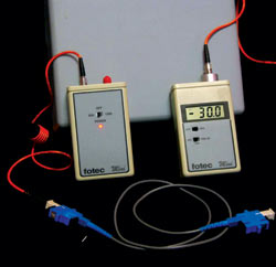
What if the optical budget works out to be close to, or more than, the loss maximum of the devices selected; in this case –12dB? There are three options to solving this problem.If the optical budget figured is close to, but less loss than the maximum, a careful installation should provide a functional system. The real-world loss of a pair of connectors is usually less than 0.5dB when tested with a loss meter and light source. Chances are that your completed fiber link will work, given careful installation and proper connector installation.
The second possibility is to contact the vendor and ask about the cost for transmit and receive devices that will carry the same signals desired with a larger maximum loss. By using higher-powered internal components, fiber optic transceiver manufacturers can readily build devices with deeper maximum loss. These special devices will cost more and may be harder to replace quickly in the event of a problem.
The most straightforward approach to a high optical budget problem is to consider the use of singlemode fiber strands instead of multimode. Singlemode has much lower loss over distance, and should easily rectify the problem. The installation planner must figure for singlemode transceivers, as the fiber type has changed, and also be prepared to install tighter tolerance singlemode connectors on each end.
Looking for a reprint of this article?
From high-res PDFs to custom plaques, order your copy today!